Pulse Width Modulation (PWM) is a technique used to simulate variable output using digital signals. Instead of varying voltage continuously, PWM rapidly switches a digital pin between HIGH and LOW, adjusting the proportion of time it stays HIGH within each cycle—the “duty cycle.” A higher duty cycle means more power delivered on average. On an Arduino, we use PWM to control things like LED brightness or motor speed by varying this duty cycle on specific PWM-capable pins.
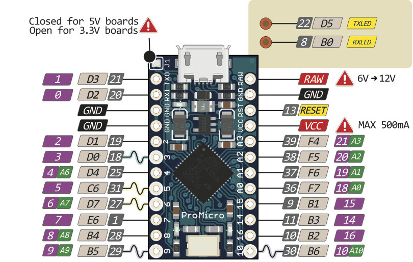
One thing, be careful to use PWM enabled pins. On the Pro Micro, these are pins 3, 5, 6, 9, & 10 (designated by the squiggly lines in the pinout diagram above). There are no additional components necessary, hook up your LED like normal using a 220Ohm resistor. The Control Surface library that we are using makes it simply to use PWM. Here is all of the code necessary to output PWM on pin 9.
NoteValueLEDPWM led = {
  9, 72,      // Pin of the LED (must be PWM pin), Midi Note 72)
};
That’s it, now the velocity of midi note 71 will determind the brightness of the LED!
multiple leds… make sure you are using PWM pins (~)
NoteLEDPWM leds[] {
  {5, 60},
  {9, 61},
  {10, 62},
};